...racing playseat or virtual reality ?
presentation video:
I start view this web site *.
After see other project like :
http://www.gamoover.net/Forums/index.php?topic=25907.0
viewtopic.php?f=37&t=842&p=7106&hilit=siki+luna#p7106
I decide to start my project.
from car demolition
(first version : wiper motor fiat 500)
from a race car driver
from a photovoltaic installer (aluminum profiles 40x40 mm)
- profili alluminio

and after some time
- primoassemblaggio

and more
now must assembly and test controller parts.
15/07/2013
with
power supply 12V 30A
Arduino UNO R3
Monster Moto Shield
some pins and a cooling fins
Assembled as you can see
if you chose not to stack the two cards:
Arduino .../... Monster
... GND .../... GND pin
..... 5V .../... 5V
.. pin 4 .../... pin 4
.. pin 5 .../... pin 5
.. pin 6 .../... pin 6
.. pin 7 .../... pin 7
.. pin 8 .../... pin 8
.. pin 9 .../... pin 9
left pot
right pot
install arduino software and driver
load firmware from Racingmat found here
viewtopic.php?t=943
mount motor for test
(before check isolation = download/file.php?id=2523 or http://vos-playseat-stephaned61.xooit.f ... e.htm#p642)
- Left Motor power attached in A1-B1
- Right Motor power attached in A2-B2
- Left pot 10k control connect in A5
- Right pot 10k control connect in A4
like reported from racingmat, prefer CERMET (ceramic + metal) track rather than cheap carbon track.
when you power on power supply and connect Arduino to usb (i use only usb 5v), motors move in middle position. if they move continuously, you must invert A4 with A5 wire.
if mount motors in opposite position remember to attach the wires in opposite ways for one motor and relative potentiometer (the centre remain in centre).
you can test motor movement with arduino serial monitor writing L00<cr>, LFF<cr>, R00<cr>, RFF<cr> and you can see move to lower and highest position.
now i have install x-sim software 3.0.x.x
in converter i configure :
- output setup the USO interface selecting the available comport (for me COM6), 8 bit resolution, binary output, 115200,8,n,1
- in datapacket : L~a01~~13~R~a02~~13~
- with the break of : from 33 to 40 ms
- Math Setup : i decide to follow the video tutorial in X-SIM 3 documents, named Professional profile making by yokoyoko with some adjustement in values
- Program setup : have enable auto start and stop triggers.
the result can see here :
next step final assembly
when i received last part:
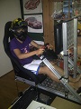
i can assembly my racing playset:
adding some pics with quotations; total weight 73kg
and after some electrical and mechanical adjustments
we decide to make first video:
now i must to improve motor's mounting
and adjust x-sim profiles for improve the playset movement.
we want to extend special thanks to:
Alfio, Jody, Luca, Matteo, Mauro, Paolo, Saverio, Walter, RacingMat and sirnoname
after a shorts tests broke both motor shafts
therefore i decide to different motor assembly and now i have this structure.
panoramic final assembly of playseat
after further problems with pots, decide to buy cermet pots
i hope have more long life
and if my mounting calibration is not perfect, buy also flexible couplings
assembled
and now other tests.
20/09/2013
after some adjustment the playseat move ok with new cermet pots, also reduce the break in USO datapaket from 60 to 40ms.
in a few days post a new video with Race07.
today decide to install a safety switch to break motor power.
this help me for a problem in power on sequence.
i have Arduino power from pc usb and 5v for pots is from arduino.
sametime in power on, my motors rotate * with the possibility of broken.
now i power on pc, attach arduino to usb, sit on playseat and release the power for motors.
21/09/2013
i decide to add a LKM1638 ver. 1.2 to my Arduino.
connect from Arduino to LKM1638 5 pins :
LKM1638 .../... Arduino UNO R3
... pin 1 .../... 5V
... pin 2 .../... 0V
... pin 3 .../... D4 (Clock o CLK)
... pin 4 .../... D5 (Data I/O o DIO)
... pin 5 .../... D3 (Strobe0 o STB0)
in actual Arduino code from RacingMat (viewtopic.php?t=1073), import code extracted from tronicgr (viewtopic.php?t=155) with some adjustment.
for upload to board, remember to download library from http://code.google.com/p/tm1638-library/
and import in arduino programmer
- Code: Select all
    /*
     Arduino code for dynamic playseat 2DOF - *banned forum, plz support the X-Sim developers by removing this link* www.X-sim.de
     Created 24 May 2011 by Jim Lindblom   SparkFun Electronics https://www.sparkfun.com/products/10182 "Example Code"
     Created 24 Apr 2012 by Jean David SEDRUE Version betatest26 - 24042012 http://www.gamoover.net/Forums/index.php?topic=25907
     Updated 20 May 2013 by RacingMat in english http://www.x-sim.de/forum/viewtopic.php?f=37&t=943 in french : http://www.gamoover.net/Forums/index.php?topic=27617
     Updated 26 Sep 2013 by Soraz for adding dashboard http://www.x-sim.de/forum/viewtopic.php?t=1103
     Updated 15 Dec 2013 by Soraz improve motor perfomance with dashboard refresh timed and other
     */

    // USO command to play : L~a01~R~a02~M~a03~S~a04~G~a05~
    // USO command to simulatorstop : Z00
    // L : left motor  (8bit - hexadecimal output)
    // R : right motor (8bit - hexadecimal output)
    // M : rpm              (16bit - binary output)
    // S : speed            (16bit - binary output)
    // G : gear             (16bit - binary output)
    // Z : clear            (to clear display and max rpm value)
    //
    // Arduino wiring
    // for motors
    // Pin A4 : pot right
    // Pin A5 : pot left
    //
    // for dashboard
    // Pin D3 : STB0 - strobe
    // Pin D4 : CLK - clock
    // Pin D5 : DIO - data

    ////////////////////////////////////////////////////////////////////////////////
    // DashBoard include
    ////////////////////////////////////////////////////////////////////////////////
    #include <TM1638.h> //can be downloaded from http://code.google.com/p/tm1638-library/
    // define a module on data pin 5, clock pin 4 and strobe pin 3
    TM1638 module(5, 4, 3);

    ////////////////////////////////////////////////////////////////////////////////
    #define BRAKEVCC 0
    #define RV  2 //beware it's depending on your hardware wiring
    #define FW  1 //beware it's depending on your hardware wiring
    #define STOP 0
    #define BRAKEGND 3

    ////////////////////////////////////////////////////////////////////////////////
    #define pwmMax 255; // or less, if you want to lower the maximum motor's speed

    // defining the range of potentiometer's rotation
    const int potMini=208;
    const int potMaxi=815;

    ////////////////////////////////////////////////////////////////////////////////
    #define motLeft 0
    #define motRight 1
    #define potL A5
    #define potR A4

    ////////////////////////////////////////////////////////////////////////////////
    //  DECLARATIONS
    ////////////////////////////////////////////////////////////////////////////////
    /*  VNH2SP30 pin definitions*/
    int inApin[2] = {7, 4};     // INA: Clockwise input
    int inBpin[2] = {8, 9};     // INB: Counter-clockwise input
    int pwmpin[2] = {5, 6};     // PWM input
    int cspin[2] = {2, 3};      // CS: Current sense ANALOG input
    int enpin[2] = {0, 1};      // EN: Status of switches output (Analog pin)
    int statpin = 13;           // not explained by Sparkfun

    /* init position value*/
    unsigned int DataValueL=512;         // middle position 0-1024
    unsigned int DataValueR=512;         // middle position 0-1024

    int sensorL,sensorR;        // for left and right pots

    // for dashboard
    int i;
    unsigned long tt;           // holds milliseconds
    unsigned int offset = -32767; // holds offset for dashboard
    unsigned int carspeed;      // holds the speed data (0-65535 size)
    unsigned int gear;          // holds gear value data (0-65535 size)
    unsigned int rpm;           // holds the rpm data (0-65535 size)
    unsigned int rpmleds;       // holds the 8 leds values
    unsigned int rpmmax = 5000; // retrieves from rpm live with minimum setting on initialization and simulatorstop
    byte speeddata = 0;         // marker that new data are available
    byte geardata = 0;          // marker that new data are available
    byte rpmdata = 0;           // marker that new data are available
    // char* neutral = "n";        // sets the character for neutral
    char* neutral = "0";        // sets the character for neutral
    char* reverse = "r";        // sets the character for reverse

    String namesz = "88888888"; // sets a custom logo start up banner
    String name = "X-Sim 3";    // sets a custom logo start up banner

    ////////////////////////////////////////////////////////////////////////////////
    // INITIALIZATION
    ////////////////////////////////////////////////////////////////////////////////
    void setup()
    {
      // serial initialization
      Serial.begin(115200);

      // initialize the screen with leds test
      // module.clearDisplay();                       // clears the display from garbage if any
      // module.setDisplayToString(name);             // prints the banner
      // delay(1000);                                 // small delay 1 sec
      module.clearDisplay();                       // clears the display from garbage if any
      module.setDisplayToString(namesz);           // prints the banner
      delay(1000);                                 // small delay 1 sec
      module.clearDisplay();                       // clears the display
      module.setLEDs(0b11111111 | 0b00000000<< 8); // all green leds
      delay(1000);                                 // small delay 1 sec
      module.setLEDs(0b00000000 | 0b11111111<< 8); // all reds leds
      delay(1000);                                 // small delay 1 sec
      module.setLEDs(0b00000000 | 0b00000000<< 8); // turn off all leds

      // initialization of Arduino's pins
      pinMode(statpin, OUTPUT); //not explained by Sparkfun
      digitalWrite(statpin, LOW);

      for (int i=0; i<2; i++)
      {
        pinMode(inApin[i], OUTPUT);
        pinMode(inBpin[i], OUTPUT);
        pinMode(pwmpin[i], OUTPUT);
      }
      // Initialize braked for motor
      for (int i=0; i<2; i++)
      {
        digitalWrite(inApin[i], LOW);
        digitalWrite(inBpin[i], LOW);
      }
    }

    ////////////////////////////////////////////////////////////////////////////////
    ///////////////////////////////// Main Loop ////////////////////////////////////
    ////////////////////////////////////////////////////////////////////////////////
    void loop()
    {

      readSerialData();   // DataValueR & L contain the last order received (if there is no newer received, the last is kept)
      // the previous order will still be used by the PID regulation MotorMotion Function

      // read actual position
      sensorR = analogRead(potR);  // range 0-1024
      sensorL = analogRead(potL);  // range 0-1024

      // move new position
      motorMotion(motRight,sensorR,DataValueR);
      motorMotion(motLeft,sensorL,DataValueL);

      // refresh digit every 260ms
      // minimum recommended 120ms
      if ((millis()-tt) > 260){
        // update dashboard
        dashboard();
        tt = millis();
      }

    }

    ////////////////////////////////////////////////////////////////////////////////
    // Procedure: wait for complete trame
    ////////////////////////////////////////////////////////////////////////////////
    void readSerialData()
    {
      byte Data[3]={'0','0','0'};
      // keep this function short, because the loop has to be short to keep the control over the motors

      // parse the buffer
      if (Serial.available()>2){
        Data[0]=Serial.read();                   // read command
        if (Data[0]=='L'){                       // if right motor data
          Data[1]=Serial.read();                 // store high byte
          Data[2]=Serial.read();                 // store low byte
          DataValueL=NormalizeData(Data);        // converts the hexa in decimal and that maps the range
          if (Serial.available()>2){
            Data[0]=Serial.read();               // re-read command
          }
        }
        if (Data[0]=='R'){                       // if left motor data
          Data[1]=Serial.read();                 // store high byte
          Data[2]=Serial.read();                 // store low byte
          DataValueR=NormalizeData(Data);        // converts the hexa in decimal and that maps the range
          if (Serial.available()>2){
            Data[0]=Serial.read();               // re-read command
          }
        }
        if (Data[0]=='M'){                       // if rpm data
          Data[1]=Serial.read();                 // store high byte
          Data[2]=Serial.read();                 // store low byte
          rpm = ((Data[1]<<8) + Data[2]);        // concatonate bytes (shift 8 bits)
          rpm = rpm + offset;                    // offset
          rpmdata=1;                             // we got new data!
          if (Serial.available()>2){
            Data[0]=Serial.read();               // re-read command
          }
        }
        if (Data[0] == 'S' ){                    // if speed data
          Data[1]=Serial.read();                 // store high byte
          Data[2]=Serial.read();                 // store low byte
          carspeed = ((Data[1]<<8) + Data[2]);   // concatonate bytes (shift 8 bits)
          carspeed = carspeed + offset;          // offset
          speeddata=1;                           // we got new data!
          if (Serial.available()>2){
            Data[0]=Serial.read();               // re-read command
          }
        }
        if (Data[0] == 'G' ){                    // if gear data
          Data[1]=Serial.read();                 // store high byte
          Data[2]=Serial.read();                 // store low byte
          gear=((Data[1]<<8) + Data[2]);         // concatonate bytes (shift 8 bits)
          gear = gear + offset;                  // offset
          geardata= 1;                            // we got new data!
        }
        if (Data[0] == 'Z' ){                          // if simulatorstop
          Data[1]=Serial.read();                       // store high byte
          Data[2]=Serial.read();                       // store low byte
          rpmmax=5000;                                 // reset rpmmax
          module.clearDisplay();                       // clear display
          module.setLEDs(0b00000000 | 0b00000000<< 8); // clear leds
        }
      }
      if (Serial.available()>40) Serial.flush();
    }

    ////////////////////////////////////////////////////////
    void dashboard()
    ////////////////////////////////////////////////////////
    {
      if (speeddata == 1) {
        // filter of negative value
        // reported from 65535 to down in Richard Burns Rally
        if (carspeed > 50000){                            // reverse velocity in some games are negative value
          carspeed = 65536 - carspeed;                    // convert positive with 16bit value
        }
        module.setDisplayToDecNumber(carspeed, 0, false); // displays numerical the speed
        speeddata=0;
      }
      if (geardata == 1) {
        if (gear >= 1 and gear <10 ){
          module.setDisplayDigit(gear, 0, false);         // displays numerical value of the current gear
        }
        if (gear == 0){
          module.setDisplayToString(neutral, 0, 0);       // displays the character for neutral
        }
        if (gear == (65535)){                             // -1 that reprecents reverse rollover so...
          module.setDisplayToString(reverse, 0, 0);       // displays the character for reverse
        }
        geardata=0;
      }
      if (rpmdata == 1) {
        // auto set max rpm
        // with filter of negative value
        // reported from 65535 to down in Kart racing Pro
        if (rpm>rpmmax && rpm<50000) {
          rpmmax=rpm;
        }
        rpmleds = map(rpm,0,rpmmax*1.1,0,9);              // distributes the rpm level to the 8 leds + 1 for shift change
        if (rpmleds==0){
          module.setLEDs(0b00000000 | 0b00000000<< 8);
        }
        if (rpmleds==1){
          module.setLEDs(0b00000001 | 0b00000000<< 8 );
        }
        if (rpmleds==2){
          module.setLEDs(0b00000011 | 0b00000000<< 8 );
        }
        if (rpmleds==3){
          module.setLEDs(0b00000111 | 0b00000000<< 8 );
        }
        if (rpmleds==4){
          module.setLEDs(0b00001111 | 0b00000000<< 8);
        }
        if (rpmleds==5){
          module.setLEDs(0b00011111 | 0b00000000<< 8);
        }
        if (rpmleds==6){
          module.setLEDs(0b00011111 | 0b00100000<< 8 );
        }
        if (rpmleds==7){
          module.setLEDs(0b00011111 | 0b01100000<< 8 );
        }
        if (rpmleds==8){
          module.setLEDs(0b11111111 | 0b1111111111<< 8 );
        }
        rpmdata=0;
      }
    }

    ////////////////////////////////////////////////////////
    void motorMotion(int numMot,int actualPos,int targetPos)
    ////////////////////////////////////////////////////////
    {
      int Tol=20; // no order to move will be sent to the motor if the target is close to the actual position
      // this prevents short jittering moves
      // could be a parameter read from a pot on an analogic pin
      // the highest value, the calmest the simulator would be (less moves)

      int gap;
      int pwm;
      int brakingDistance=30;

      // security concern : targetPos has to be within the mechanically authorized range
      targetPos=constrain(targetPos,potMini+brakingDistance,potMaxi-brakingDistance);

      gap=abs(targetPos-actualPos);

      if (gap<= Tol) {
        motorOff(numMot); //too near to move
      }
      else {
        // PID : calculates speed according to distance
        pwm=195;
        if (gap>50)   pwm=215;
        if (gap>75)   pwm=235;
        if (gap>100)  pwm=255;

        // if motor is outside from the range, send motor back to the limit !
        // go forward (up)
        if ((actualPos<potMini) || (actualPos<targetPos)) motorGo(numMot, FW, pwm);
        // go reverse (down)
        if ((actualPos>potMaxi) || (actualPos>targetPos)) motorGo(numMot, RV, pwm);

      }
    }

    ////////////////////////////////////////////////////////////////////////////////
    void motorOff(int motor){ //Brake Ground : free wheel actually
    ////////////////////////////////////////////////////////////////////////////////
      digitalWrite(inApin[motor], LOW);
      digitalWrite(inBpin[motor], LOW);
      analogWrite(pwmpin[motor], 0);
    }

    ////////////////////////////////////////////////////////////////////////////////
    void motorOffBraked(int motor){ // "brake VCC" : short-circuit inducing electromagnetic brake
    ////////////////////////////////////////////////////////////////////////////////
      digitalWrite(inApin[motor], HIGH);
      digitalWrite(inBpin[motor], HIGH);
      analogWrite(pwmpin[motor], 0);
    }

    ////////////////////////////////////////////////////////////////////////////////
    void motorGo(uint8_t motor, uint8_t direct, uint8_t pwm)
    ////////////////////////////////////////////////////////////////////////////////
    {
      if (motor <= 1)
      {
        if (direct <=4)
        {
          // Set inA[motor]
          if (direct <=1)
            digitalWrite(inApin[motor], HIGH);
          else
            digitalWrite(inApin[motor], LOW);

          // Set inB[motor]
          if ((direct==0)||(direct==2))
            digitalWrite(inBpin[motor], HIGH);
          else
            digitalWrite(inBpin[motor], LOW);

          analogWrite(pwmpin[motor], pwm);

        }
      }
    }

    ////////////////////////////////////////////////////////////////////////////////
    void motorDrive(uint8_t motor, uint8_t direct, uint8_t pwm)
    ////////////////////////////////////////////////////////////////////////////////
    {
      // more readable function than Jim's (for educational purpose)
      // but 50 octets heavier ->  unused
      if (motor <= 1 && direct <=4)
      {
        switch (direct) {
        case 0: //electromagnetic brake : brake VCC
          digitalWrite(inApin[motor], HIGH);
          digitalWrite(inBpin[motor], HIGH);
          break;
        case 3: //Brake Ground (free wheel)
          digitalWrite(inApin[motor], LOW);
          digitalWrite(inBpin[motor], LOW);
          break;
        case 1: // forward : beware it's depending on your hardware wiring
          digitalWrite(inApin[motor], HIGH);
          digitalWrite(inBpin[motor], LOW);
          break;
        case 2: // Reverse : beware it's depending on your hardware wiring
          digitalWrite(inApin[motor], LOW);
          digitalWrite(inBpin[motor], HIGH);
          break;
        }
        analogWrite(pwmpin[motor], pwm);
      }
    }

    ////////////////////////////////////////////////////////////////////////////////
    // Function: convert Hex to Dec
    ////////////////////////////////////////////////////////////////////////////////
    int NormalizeData(byte x[3])
    ////////////////////////////////////////////////////////////////////////////////
    {
      int result;

        // x1
        if ( x[1]>47 && x[1]<58 ){//for xA to xF
          x[1]=x[1]-48;
        }
        if ( x[1]>64 && x[1]<71 ){//for x0 to x9
          x[1]=x[1]-55;
        }
        // x2
        if ( x[2]>47 && x[2]<58 ){//for xA to xF
          x[2]=x[2]-48;
        }
        if ( x[2]>64 && x[2]<71 ){//for x0 to x9
          x[2]=x[2]-55;
        }
      // map the range from simulator (0 <-> 255 - 8bit data) to the mechanically authorized range (potMini <-> potMaxi)
      result=map((x[1]*16+x[2]),0,255,potMini,potMaxi);
      return result;
    }
and converter setup
Output Setup USO - RPM, Speed, Gear (16 bit, binary output)
Output Setup USO - Command
with this string also change my left and right axis from 'binary output' to 'hexadecimal output'
in simulatorstop add Z00 to some reset needed if change car or game without reload Arduino code
Math setup (0-32768) for Speed (Extractor input:56), RPM (Extractor input:57), Gear (Extractor input:60)
i test this code with Race07, Kart Racing Pro and Dirt2
a sample video :
23/09/2013
post video with Race07 with cermet pots, dashboard (with same Arduino for wiper motor) and last profile with roll, pitch and vertical force (thanks to yokoyoko).
26/12/2013
added handbrake :
i have attach a micro-switch in parallel of a button inside the steering whell
05/01/2014
added blue led strip
before .................. after