

- Joyrider

The early stages of my sim can be found here.
――――――――――――――――――――――――――――――――――――――――
My Joyrider Project Comes to a Life
by value1 on 12.11.2011, 22:38
Finally – after gone through hydraulics, servo and AC motors, actuators, real life measurements, 3DoF, 2DoF, welding course, etc. – my sim is coming to a life.
- Platform Hardware

Re: My Joyrider Project Comes to a Life
by value1 on 21.12.2011, 23:35
Today I kicked out the wipers. They stalled at 9V/18A I mounted a winch (Arwin TRC9202) instead. Man is it noisy and screams for a good headphone
But it has the power! It easily moves my 25 kg sandbag up and down
This is the Christmas present for me.
- Winch/Chain Drive

Re: My Joyrider Project Comes to a Life
by value1 on 28.01.2012, 22:12
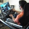
Today for the first time I drove up the Klausenpass with my 1DoF sim
It finally moves back and forth with me in the seat and the 40" screen in front. What a feeling! Still needs some tweaking of the settings – and the roll axis…
The 12V winch works great in combination with the Jrk. The bicycle chain drive probably needs changing at a later stage.
I will post some pictures later.
Re: My Joyrider Project Comes to a Life
by value1 on 31.01.2012, 21:29
Here some video footage.
At this stage the joyrider is very much a proof of concept. The Jrk is fantastic easy, all the components work nicely together, the winch can handle the ±36° up and down easily (18-20 A consumption max. so far)!
Several things will need adjustment:
• The gear ratio of the drive must be lower, i.e. the movements are too slow.
• The backlash is hilarious. The bicycle chain is not the most efficient way to drive this platform. A timing belt might be better.
• The computer needs an upgrade. The poor little Pentium®4 @ 3 GHz with rFactor @ 1920x1080, x-sim Sender and Profiler running is by far overloaded
• The second axis must be constructed. A 1DoF is not worth the effort – although it's quite impressive how much more you feel like driving with the movement.
• Tidy up the cables and paint the rosty steel…
More to come…
- Overview

- Bicycle Chain Winch Drive

Re: My Joyrider Project Comes to a Life
by value1 on 11.03.2012, 00:05
Some update on my project.
I have installed the second axis (roll). Instead of a chain drive I (remember the hilarious backlash ) I designed a lever drive.
- Roll axis

Unfortunately the combination of weight (180 kg including the pilot), centre of gravity (above the axes) and the power of the winch is not good enough to allow to move the joyrider sufficiently and it even stalls in the end positions (left and right)
It looks like the backlash of the lever drive is not any better than the chain drive. And the backlash even grows as the gears wear (really soft steel of the winch gear!).
At least the design allows a nice placement of the potentiometers in the axis of rotation rather than somewhere on the winch. This should allow me better control of the movement – in theory.
- Potentiometer

Thanks to the hint of pippo978 to SketchyPhysics, I have drawn a dynamic model of my sim.
 SimPlatform %28Google Sketchup skp file%29.zip
- (1.55 MiB) Downloaded 813 times
You'll need Google Sketchup and SketchyPhysics to display and move the sim.
I'll have to resolve the issue with the lack movement – probably go back to the drawing board...
Re: My Joyrider Project Comes to a Life
by value1 on 18.03.2012, 20:42
Not that it would necessarily matter to you but still it was big fun: I had a ride on a ForceDynamics 401 today at the Geneva Motor Show and it was fabulous.
- Force Dynamics 401

Re: My Joyrider Project Comes to a Life
by value1 on 14.04.2012, 17:51
Sometimes I wonder, how the eff you guys have ever completed your sims!
Tonight after the whole day in the workshop I realise that with the new low-axes-construction (→ add the extra tubes, move the drives, replace the sensors, etc. etc. etc.) my racing seat, that fitted nicely on the platform before, is now too wide (or the platform too narrow of course).
So I will have to cut the sim in half and broaden it a few cm.
Goodness!
(Still big fun anyway )
Re: My Joyrider Project Comes to a Life
by value1 on 19.05.2012, 22:19
Yes, I did some basic FE calculation of my original design and the outcome was that by no means I would be able to move the platform more than a few degrees with the winch motors. So I decided to follow the advice of several of you and go through a redesign. The axes now pass through the centre of gravity rather than below it. It meant that I had to add tubes all over.bsft wrote:Nice design there, I still suggest lowering the middle frame to improve centre of gravity though, that may help increase movement.
- Comparison old vs new version

- Overview new design

I have uploaded two videos:
One on the famous great Klausenpass
,
the other on my favourite Dirt2 Croatia track..
The roll axis in curves feels great! The acceleration/deceleration didn't convince me yet. One thing I noticed: there is hardly any shaking when driving over uneven ground.
Someone has a sugestion how to improve this?
(I probably should start reading the x-sim manual )
Re: My Joyrider Project Comes to a Life
by value1 on 22.05.2012, 23:29
Here some comparison date of the telemetry extracted from rFactor, the output of x-Sim² and the actual reaction of my sim (measured with a 6DOF sensor).
- Acceleration

The measured values match the x-sim² data nicely for the two controlled axes (X and Y axis). Obviously the maximum acceleration is not yet reached as I have not fully calibrated the platform. I should be able to reach 0.6 g with maximum displacement.
The vertical accelerations don't match yet - looks like random data. The x-sim² output is much more dynamic than the actual movement of the sim.
One actually misses the feeling of the cobblestone pavement in the first two curves of Klausenpass.
――――――――――――――――――――――――――――――――――――――――
It's a mixture of all different kinds of thoughts I leverage from the forum here. Thank you all, guys, for your help and your projects shared!
After all I plan now to use 2 wiper motors driven by jrk's (too lazy/busy/scared for Tronic's AMC motor motion-controller with pwm/servo output)
The screen shall be attached to the inner frame as well as the seat. The theoretical pitch angle is 30°, which is 0.5g. Let's see what the motors can stem.
The motors shall pull 2 steel cables connected to the inner and outer frame. Geometric details still to be worked out.
I will keep you posted about the progress.
Thomas
Here some pics of the metal frame.
- Base frame

- Outer Frame, side acceleration (roll), 18.4 kg
, 18.4 kg / Outer Frame.jpg")
- Inner Frame, acceleration, braking (pitch), 16.7 kg
, 16.7 kg / Inner Frame.jpg")
- Assembled frames

- Axis with integrated cogwheel

- Fixture of potentiometer (pitch)
 / Fixture of potentiometer.JPG")
- Screen Frame, 14.4 kg

- Seat (6.7 kg) and pedals (5.3 kg) on OSB (Oriented Strand Board, 14.2 kg)
 and pedals (5.3 kg) on OSB (Oriented Strand Board, 14.2 kg) / Seat and pedals.JPG")


 / Overview.JPG")