Make a Micro Donation if you find this post usefull!
Last update: 24.04.2013
The project is uploaded to the open source pages of GitHub and can be freely downloaded here: https://github.com/X-Sim/X-PID-Arduino-PID-motor-control
This is the beta release of the project and you can check in your versions with the easy github software. You will find here in the next days some additionally informations and updates like in the githup project.
Download and use the github windows frontend for an easy access. You can easily check in your changed motor shield code and improove this project.
This low cost project is a RC servo like position control for one or two geared motor(s) with a pot as angle feedback. You can send the arduino microcontroller a value from 0 to 1023 and the arduino will control the motor speed and direction to reach your target value. The PID algorithm will insure that the motor will not get into hold vibrations if the pot has some influences. This article will describe where you have to take attentions and what you have to setup to get the best results.
The project will help you to connect any arduino motor shield or other H-Bridges to the controller because it is open source and the output pins can therefor be changed as you like.
The code is hosted on GitHUB and can be easily downloaded. You can upload a better modified version and improove this article by contacting me. The project home is http://www.x-sim.de. The licence is open source but you need to relink my page if you use parts of this project. The code is for Arduino UNO boards but should work on other devices.
A windows sample source code (X-Sim plugin) is attached to show how to communicate with this board.
All the hardware stuff is common eBay hardware that can be ordered in china or local stores. For me the arduino UNO was at 17Euro and each 45A H-Bridge did cost 25Euro. The wipers are parts of the junk yard or out of the spare part automotive sector. The powersupply was out of my old computer.
In my case this setup did cost me 67€, what is my cheapest development I did.
The price can go down if you use a arduino nano which you can get for 10€ at ebay and if you use cheaper H-Bridges.
 (Note: the wiring of the above Arduino UNO picture is not the final wiring. Read the below wiring information.)
 Viewed 783180 times")
Sparksfun Moto Monster H-Bridge via eBay ~18€ + Arduino UNO ~15€.

For more detailed informations about the Moto Monster shield you must read this thread:
viewtopic.php?p=13199#p13199
Connect the powerfull Sabertooth 2x60 to the open source firmware:
Go here for the details how to connect and use the sabertooth H-Bridge with X-PID.
For firmware details read the next pages.
What you get:
- a cheap arduino platform based motion controller solution
- an X-Sim plugin with autodetection and high resolution support (USO mostly limited to 256 positions)
- full resolution support of the 1024 possible positions of the arduino ADC with the x-sim plugin
- free adjustable pin control with the open source code, every pin action has its own sub function for an easy change
- adjustable PWM frequency to reduce motor noises
- motor gain control if one motor is more powerfull than the other (simple edit code and upload)
- port renaming in X-Sim to use SCN5 profiles with the same port names (left/right actuator)
- frontend to optimize the settings of the PID controller with graphical support of the timings
- floating point engine for the PID
- high update rates of the PID with 3000 cycles per second
- free access to the source code of the plugin and the firmware with famous and easy github GUI
You will need for this project:
- a arduino UNO, nano or arduino duemilanove (another arduino can be used but you have to change the source code)
- for each motor a pot and fitting cables
- a geared motor like a wiper motor
- for each motor a H-Bridge fitting to the power consumption of your motor
- a ready installed arduino IDE for uploading the firmware
- some software like X-Sim which will send commands to the arduino via serial port
- If you like to recompile or change the windows source code you need Visual Studio 2010 professional (with MFC support).
 Firmware_and_plugin_1-4.zip
- (780.08 KiB) Downloaded 6510 times

 Viewed 783180 times")
For the test setup I decided to use a smaller motor.
Quick starter guide
1. Install the arduino software from here: http://arduino.cc/en/Main/Software
2. Get the attached ino file and the DLL file for the X-Sim interface-plugin directory
3. Plug your arduino into the USB port and follow the driver installation instructions
4. Open the windows device manager and write down the new installed comport
5. Open the Arduino IDE and open the x-pid.ino file
6. Setup the your connected Arduino in the IDE. Input the comport. You may try the LED blink example.
7. Upload the firmware to the arduino
8. copy the DLL file to the interface plugin directory of X-Sim
Thats all, now you can connect your H-Brige as described below and start X-Sim.
Long texted: Upload of the Arduino X-PID firmware
You will need to download and install the arduino software package in order to do anything with arduino. Please go to the arduino homepage and follow the basic steps for the download and driver installation of the arduino board. After you have installed the software you need to connect the arduino and tell the windows device manager where the driver is. You will get installed a new comport in the device manager which you have to write down. After you have started the arduino software you must enter this comport number into the software and try the "blink" example out of the example menu. If the upload works and the LED is blinking you can continue here, else read the arduino homepage how to solve your problems.
Next to that you need to download the current available firmware for the arduino. This is a simple txt file but has a file extension name with .ino which is loadable into the arduino software. Simple double click this file or copy the content into the arduino text box. Now you only need to compile and upload this firmware and it will start after your upload. After it has started the motor should go to the middle position. Check if the motor is moving into the wrong direction and change the motor cables +/- to correct the motor direction. At this point the pot stop pin could get dammaged if you did not removed it like explained below.
360° Full turn option:
If you own a simulator with full turn you have the problem that from 360 to 0 degree the simulator will turn back instead of a full turn.
Go into the ino file with your arduino framework and find the following lines:
//360° option for flight simulators
bool turn360motor1 = false;
bool turn360motor2 = false;
There you can enable the case decition for each motor. the top quarters will then be controlled to the next position and will make a full turn. A pot with full turn option is needed (HALL, magnetic etc.)
Screenshots of firmware upload:
 Viewed 783260 times")
 Viewed 783260 times")
Test your PID controller with X-Sim:
For the first run you should switch both power offsets to zero (2x right for each output) and the PWM frequency to 3kHz (round buttons top right).
Start the X-Sim Converter.exe application. After it has started you should see the arduino in the interface setup. You can open the setup dialog by double clicking the X-PID entry on the right side. Remove the power of the motor and setup your minimum and maximum values if you could not solve a mechanical solution for a 100% pot way usage. Move the X-PID window to the side to see the interface setup. Select your motor output and enter 10% or 90% in the value box. Now you can press the "Set Output" button and your controller should drive the motor to its new position.
For further setup you must read the pololu thread, which use the same procedure: viewtopic.php?f=39&t=673
 Viewed 784528 times")
 Viewed 784528 times")
PID tuning:
Open the X-Sim plugin in the interface setup with a doubleclick on the left shown "X-PID" entry and you will see the settings for one arduino board. You can select your arduino output and enter a 90% value. If you press "SetOutput" and "ClearOutput" you can test your movement for the PID adjustment very well. You may also use the slider panel of the extractor application which is able to make sawtooth signals.
For PID tuning you have to set down the power offset to zero and you have to follow the next steps.
For manual tuning, set all three constants to zero, then turn up Kp until oscillation occurs. Then turn up Kd until oscillation disappears. Adjust Kd until the system is critically damped, i.e. there's no overshoot. Then increase Ki until the steady-state error goes to zero in a reasonable time.
Pot software adjustment:
If you test your setup or cannot solve the below noticed mechanical pot mounting you have to do the software pot adjustment in the X-Sim plugin. This means you will loose some reachable positions. You have to move your actuator or geared motor to the maximum position and press the maximum button (you can see the current value inside the plugin). After this you have to move your actuator to the minimum position and press the minimum button. The values are stored in the controller and therefore a reinstall of the X-Sim software will not delete this adjustment. You have to insure the minimum is not 0 and the maximum is not 1023. A offset of 2 will insure a better working PID control in the extreme positions. Also a limiter in the software can make better results.
Hardware wiring:
You need to have a look into the x-pid.ino file. There you find which pin is connected to which pin of the H-Bridge, the pot and the motor. The above pictures do only give you a small imopression how the cables need to be placed but the ino file will tell you the exact position. If the motor is moving in the wrong direction or it seems to work wrong, you can simple switch the motor cables and it should work. This means you can connect the GND and 5volts of pot as you want and correct the motor connections if it was the wrong direction. If the motor control is working but in the wrong direction you can switch motor cables and pot cables or you invert the output in the X-Sim math section.
Hardware requirements
Pot buy instructions:
As pot you need any linear pot (no logarythm audio pot) out of the market from 5kOhm to 100kOhm (standard is 47kOhm). The pot must have three connectors. You have to connect the middle connector (the sliding contact) to the arduino analogue input port. This is the "analogue to digital" converter port of the arduino. The standard is analog port 0 (A0) for motor controller 1 and A1 for controller 2.
The downloadable firmware is open source and you can simple rename the port number as you like.
The other two pins of the pot have to be connected to GND and +5V of the arduino connectors. You can verify the pot with the X-Sim plugin, which will display you the current pot position in a value from 0 to 1023.
The pot has to show you 0 volts (or 0 in X-Sim) at the start, 1.25 volts (or 255 in X-Sim) at 1/4 of the pot way, 2.5 volts (or 511 in X-Sim) at 1/2 of the way, 3.75 volts (or 766 in X-Sim) at 3/4 of the way and 5 volts (or 1023 in X-Sim) at the end of the pot way. If this is not the case you have a logarithm pot that cannot be used. Buy pots which are dust save or insure that no dust can reach the pots.
Pot wiring:
The pot will output a voltage from 0 to 5 volts. The Arduino analogue to digital converter will convert this voltage to a value of 0 to 1023 which means each step has below 5 millivolts. This small voltage get very easy in influence to motor interferences on the power lines. You must keep the cables as short as possible (5cm) or use shielded cabled with three internal cables and one shield. The cables must be mounted far away from the motor housing or the motor power cables. The cable shield is only connected to the arduino GND pin. Do not use shielded cables longer than a half meter. Additionally you MUST generally insure that the motor GND (=minus pole) is never connected to the frame or to the computer GND. You can measure this with a multimeter from the motor connector to the GND pin of your arduino board. This is also a importand part of the used H-Bridge. Motors above 2 Ampers do have big interferenced to the computer and may damage it or may hangup the computer with a big electro pulse.
Pot hardware mounting:

You have to mechanical connect the pot to the output axis of the geared motor. This means you have to fullfill some mechanical basics. The first basic is that you have to remove the pot end stop from the pot. If you do not remove the stop the pot may get damaged if the motor is not adjusted and may drive against this end stop. In the best case you can open the pot and you can remove the plastic element of the end stop with a side cutter. Then you can check if the pot can be free move over the 360°.
The second mechanical basic is the 100% usage of the pot angle. This means you have to insure the complete pot angle is usable and you can use the 0 to 1023 ADC values without the usage of the X-Sim feedback pot adjustment. Do not try to decrease the pot resolution by using a limitation, this should be the last option you try. Every resolution limitation will reduce the reachable positions of your controller which is limited to 1024 positions of the pot ADC converter.
You can reach this goal with many solutions, I will now explain two of them. Solution one is to connect the pot directly to the geared output axis (not to the motor axis). In case of a simulator you do not need the 210-360° of the pot, you need only about 0 to 170°. Now you have to insure the pot will output 0 to 5 volts for the ADC value of 0 to 1023. This can be done with open the pot and paint the not needed slider way with electric leading paint. This is metallic lacquer out of the automotive spare part section (i.e. Auromal 38). It is used to repair the back window heating elements. You need to paint the not needed areas of the pot with this silver metallic lacquer and wait until it is dry. You can paint a little bit more than you need and then mount the pot and move it from the maximum to the minimum position. The sliding contact will remove the lacquer from the end positions and you can then remove the not needed lacquer where the pot was. After this you should overpaint the metallic laquer with 2 component epoxy glue to insure it will not get detroyed of the pot will get overdrilled by 360° and a not adjusted PID control. After you have finished this work you can measure a lower resistor value between the two (non slider) pot connections and you get 0 to 5 volts ont the middle connector.

Option two is something for RC car or plane model builders. You can reduce the pot movement by using gears on the same axis output as above. You have to go to the next local RC model dealer and calculate the exact fitting gear transmission. Insure you have 0 t 5 volts if you move the motor from the minimum to the maximum.
H-Bridge reqirements:
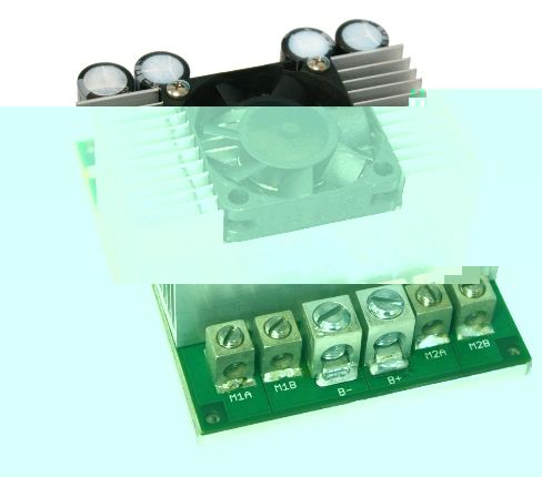
A H-Bridge is a MOSFET or transistor power amplifier for the motor. It has two pins for the direction and one pin for a enable pin. The enable pin is also often noticed as PWM input. Dual H-Bridges have of course the doubled count of this pins, for each H-Bridge the same pins. The direction pins are normally noticed as inp1 and inp2 which means input1 and 2. Pins for the error response of a H-Bridge are not used in this project. Professional developers do have to make use of them in their own setup. Do not trust the ampere number on the datasheets. The board developer of a H-Bridge use parts that are save for i.e. 45 ampers but do only solder connectors which can handle 2 ampers. For example the above H-Bridge has that most common blue screw connectors which can reach only 2 ampers. Same with the board layout and the width of copper on the board. You may need to solder the power cable directly to the board.
Arduino motor shields will only work if you change the code to the used pins, each motor shield has another pinout. Maybe some of you offer a changed motor shield code to be uploaded to the open source repository.
As power supply you can use a car battery or a switching power supply with low noise and low inrush current spikes. Most of the H-Bridges do not come with ready installed heatsinks. You have to connect them as soon as possible and you may use fans to cool them down.
You have to use the fitting diameter of the cables for powerful motors.
Look out for this nice imports:
- ebay 43A single bridge for one motor from china, 17$ with shipping

http://stores.ebay.de/kuyaya520?_trksid=p4340.l2563
http://stores.ebay.de/1984yht888?_trksid=p4340.l2563
Optocupler and galvanic parting:
You may need a galvanic parting of the H-Bridge ground to the PC/USB ground. Some H-Bridges have this implemented, you can give it a try. Motors below 2 ampers may work without such a board. In my example I do not use such a board and I have successfully used big motors above 2A without the galvanic parting but it is not a sure electrical solution. Simple ask otheres what they have tested in our X-Sim project gallery. It depends on the used motors and H-Bridges. Insure the motor GND power line is away from the frame or arduino GND. For professional industrial use you need a galvanic parting!
Arduino buy reqirements:
The code is written for a arduino UNO R3 and successfully tested on arduino UNO R2, arduino nano V3.0 and arduino duemilanove. Some older boards may have serial port problems in the here used 115200 baud rate. For this you can change the source code to lower baud rates by changing the comment out symbols in the .ino file. All other arduino with Atmega 328p compatible boards should also work with some attention. You need the latest drivers, the fitting FTDI settings if you use a arduino with FTDI USB/RS232 converter chip. The code is written for a Atmel328p microcontroller but can be rewritten for the other arduino boards by your own.
Sparksfun Moto Monster modification:
- motomonster1.jpg (16.22 KiB) Viewed 766534 times
The well known moto monster does not come with much power but some builders still use this board. You can use this bridge with a firmware source code modification. The modification can be also downloaded from github. It is the branch "moto monster", you can select this branch in the github webpage with a dropdown box.
Moto Monster branch with INO file you will find here
Instructions and Wikipedia
You must use this firmware instead of the master firmware that drives other H-Bridges. The other parts are the same and the firmware is detected as X-Pid 2.x in the interface setup. Please insure you remove used USO comport entries of other projects, the X-PID firmware does come with own plugins and do not use USO at all. You will get a fully featured setup for your moto monster shield with much new parts like power off, pot scaling, graphically user interface with PID tuning graphs and a very high update rate for simulating vibrations. The arduino will be autodetected on any virtual comport. More than one board is supported and also you can enable the 360° feature like above.
You find in the wikipedia and at Sparksfun another test firmware code which moves your motor continous left and right. Use this code for testing the H-Bridge is getting warm and attach a heatsink of it does. Do not continue to drive your motor without a heatsink to the moto monster shield!