|
Using Dyadics SCN5 servo linear actuators with X-Sim²
This is a description for the questions about how to wire and connect a SCN5 actuator to the PC.
NOTE: Questions about the software plugin can followed below.
The software description may also include some possible error finding solutions ...
Ok, let's start ...
This is all that you will need:
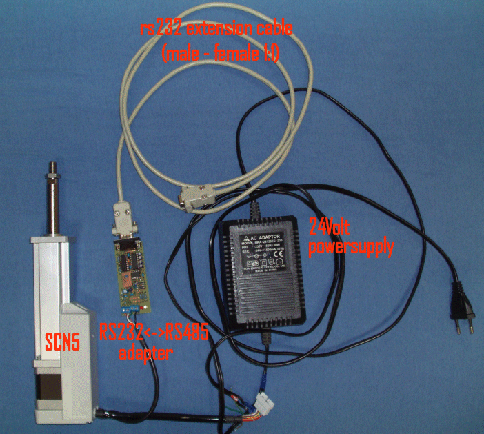
First you have to connect a SCN5 to a comport or USB virtual comport. This is done with a RS232<->RS485 adapter or a USB<->RS485 adapter or a cheap USB<->RS232 adapter followed by a RS232<->RS485 adapter.
If you want to buy or build such a adapter you can choose a auto adapter with fast TXD switching to be compatible with the TVBST SCN5 Tools of the developer. That means, you can also use their software like you are using their ADP-1 RS232 to RS485 adapter. (Or you simple buy such one from the SCN5 developer)
The RS232 converter is a "half duplex" serial device, this means it can only send OR receive. To tell the adapter to write some pins are switched on the serial port. These two are DTR pin and RTS pin in. If using a "auto" a special extra circuit will detect a TXD signal and switch without the use of DTR or RTS.
If you have a manual DTR/RTS adapter, you must find out which combination will switch to the sending mode. The x-sim SCN5 plugin carries therefore a possible invert funktion of both, DTR and RTS signal. There are 4 combinations possible. This because every combination is on the market available.
If using a "auto" adapter you have to find out the TXD switching delay time the adapter needs to switch back to the receiving mode if it has send something. This is different from hardware dealer to hardware dealer and has no standards. The auto adapter shown below has a switch to select some speeds. The normal setting for this "auto" adapters is 3ms, you can also take +/-5ms. To tell the plugin the speed, you must input this to the SCN5 plugin in X-Sim profiler2.
On "auto" adapters there may be no external powersupply. The developer sometimes uses the DTR and RTS signal as power supply.
Let me explain how: If you switch DTR high, you got +8Volt, and if you switch RTS low you got -8Volts, therefore you
got a low current power supply with 16Volts. To simulate this the two check boxes "switch RTS" and "switch DTR" are
added since 2.0.5.8 . So if you are using a "auto" adapter like the original ADP-1, you have to disable the manual mode by
disable both check boxes and find the right combination of the "invert DTR" and "invert RTS" check boxes until the adapter works.
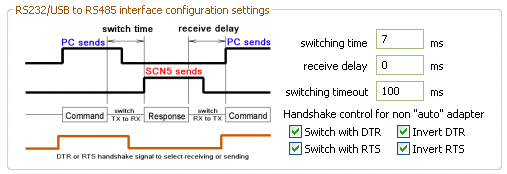
One hint here to the "auto" mode: 100ms = 10 updates of actuator per second does not make sense.
The following hardware adapter are tested successfully
Dyadic "auto"matic RS485 adapter hardware ADP-1 from the developer of SCN5

If you have bought the equipment if the original SCN5 hardware you have to do following settings:
The "auto"matic RS485 adapter hardware DIY
I have used this "auto" adapter from a elector magazine:
Hardware setting for my test: all switches on, do not mount the green LED!
I have not equipped the 7805 Low Drop power chip, because the SCN will provide stable 5 volts. (Bridge pin 1 to 3 instead of 7805 chip and D1 is a bridge)
Also I have not equipped the zener diodes, because no electrical mismatch can work here.
other have to followed and presented in this thread first page!
Wiring:
To connect the SCN5 you must know, that the wires described in the SCN5 manual with colors are only valid for the long adapter cable. It is NOT the description of the short SCN5 cables out of the white box.
Here is the wiring for the upper adapter:
SCN5 connection diagram with killswitch and ilk protection.GIF
Without killswitch (not recommended):
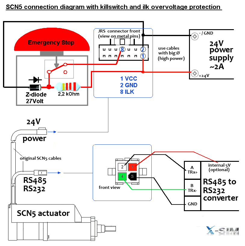
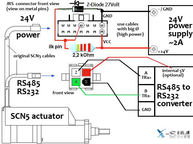
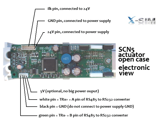
The ILK protection is very important, insert Z-Diode and resistor
4 wire cable = Termibus/RS485
Black to GND of RS485 adapter
Red to 5V of RS485 adapter (the SCN5 provides the 5Volts if powered)
White to RS485- A connector
Green to RS485- B connector
HINT: if you use the longer cable, you have to terminate the other end of the cable with 120Ohm resistor between A and B.
Settings:
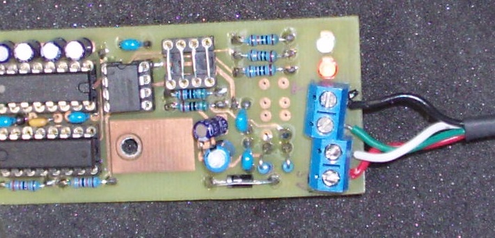
The cheapest handshake (manual) DTR/RTS RS485 adapter hardware DIY
with release 2.0.5.9 and up here is the cheapest converter available.
It will switch with the DTR pin of the RS232 connector, but because windows is no realtime system the switch cannot really
switched correctly every time. If the CPU has much load there may be output losses if you drive it too strength (fast).
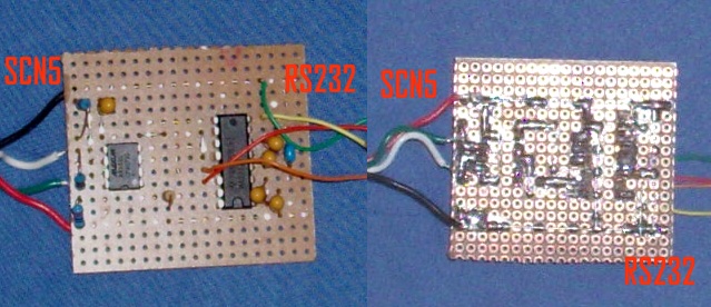
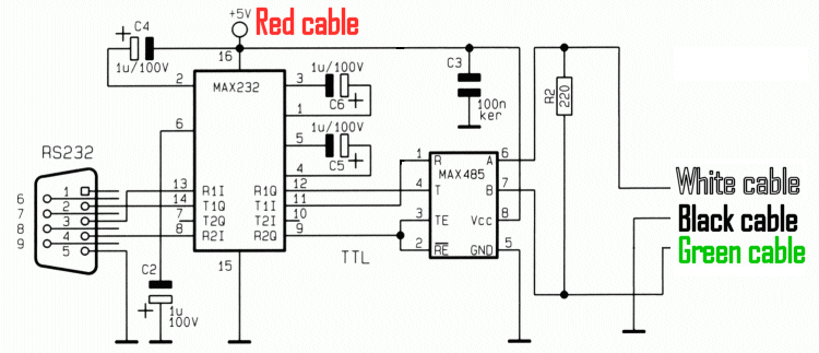
This adapter can be made without etching a board on a simple breadboard you see.
You will need twice of them, if you do not change the SCN5 device ID's.
Settings in the SCN5 setup are therefore:
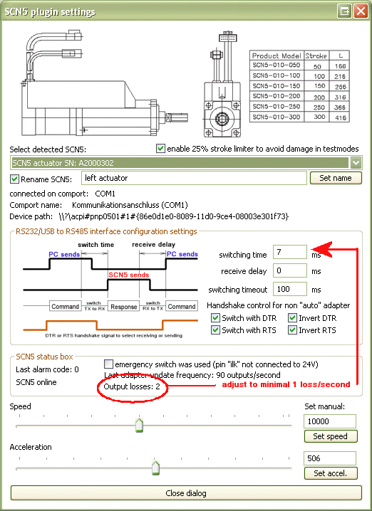
There may be output losses (only displayed in DTR/RTS mode), because windows has much cpu load and cannot switch fast enough. This is not really a problem but should be reduced by setting higher switching delay times. It is also a good choice to use a additional small pc (slow old worker pc) for the profiler work. This will always increase the movement stability and frees cpu load from the gaming pc.
14 wire powercable and PIO output cable modification (everytime needed)
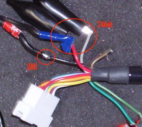 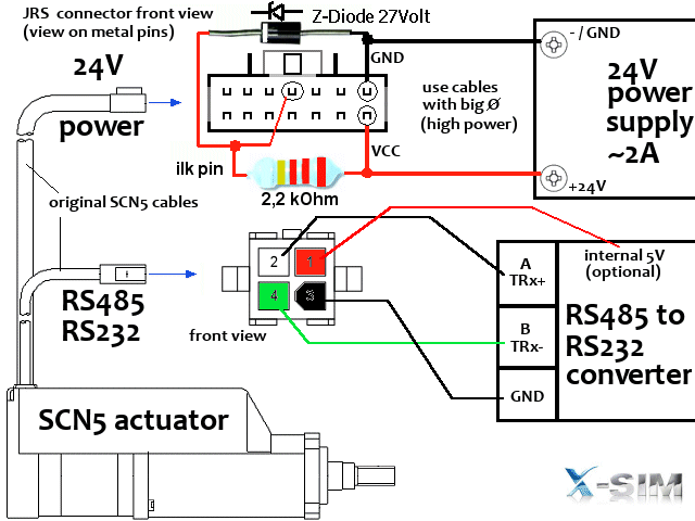
outer Red wire to +24Volt
inner Red wire = not connected
outer single black wire to Ground 24Volt (The grounds of RS485 and Termibus are not connected)
gray wire (middle) to 24Volt, this is the ilk wire for emergency stop switcher !! a button is needed which cut the 24 volts.
The power supply needs about 2 ampere current.
Mine is from the old Rock'n'Ride Interface.
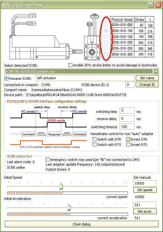
Which length of SCN5 actuators are supported?
All are supported, you can program them with the original software to other length or reduced length.
The plugin will read out the borders and calculate the X-Sim2 own unsigned integer 2³² positions automatically.
If there is one not listed because it is newer, it would be working ...
If you see a false length than you have ordered, the internal EEPROM is programed false, you should reprogram them to the right length.
Hints for ready bought RS485/RS232 converter and HowTo buy such a converter
First I have to say, that nearly all converter are connectable with the X-Sim2 SCN5 plugin. But because of the nearly unlimited versions on the electronic market this is a very difficult setup for beginners. If you cannot make a DIY (do it yourself) version as above and cannot buy the listed ones you have to look at your next suplier what is possible to get. This is a DIY forum, so you are able to choose your solution by yourself and can discuss about it here as you like. But you always need some patience with the self-made problems by buying a unknown adapter.
Here is a list what you have to know about your adapter, if you want to make a setup with a unknown adapter:
1. Is it self powered or is there a power supply added?
Self powered adapters are a bad option for beginners and you have to switch the DTR and RTS check boxes to the fitting position. If the adapter is using DTR, you have to insure DTR is always on and otherwise RTS. Some adapters need both always enabled. It make no sense to continue without a sure power. Please first measure out that with a multi meter in the opened adapter. For example at the RS485 IC VCC and GND pin. If the power will float while the profiler starts it is not the solution, the power must be surely fixed. So a powered adapter would help you in this case to avoid that unknown setup.
2. Is the adapter a half duplex RS485 converter?
This you can find out with the count of outputs (Ground and 5 volts excluded). If there are 4 wires called R+/R- and T+/T- this adapter is the wrong full duplex adapter. You need a converter with 2 wires called TRx- and TRx+ for example or called A and B.
You only can use half duplex adapters because the SCN5 Termibus is half duplex!
3. Is the adapter half-duplex mode "auto"mated or controlled by the handshake signals?
If it is "auto" the manual inludes some notice about that. This could be "TXD auto switching" or "fast autoswitching" notice. Also it MUST be a fast switching converter in the auto mode. If there is no notice it is normaly a converter that will switch the half duplex mode from send to receive with the RS232 DTR or RTS signal. To find out that importand wire, you can tryout all possible combinations of the plugin or open your adapter and look at the connector which wires of the RS232 side are used. It is up to you to find out what your adapter needs. So a auto mode converter is a better solution. You are able to change TRx+/TRx- signal pins for tryouts as you like, you cannot destroy your adapter with a false reversed connection.
4. There must be some end resistors placed!
As the above schematic (handshake adapter) the TRx+ wire and TRx- wire (or called A and B) of RS485 are equiped with a end resitor of about 120 to 220 ohm. On short cables (1m) there is only one needed at the converter side. Some converter have such a resistor included, some not. You can measure them out or the manual tells you how to enable them. For beginners a short cable and a 220ohm resistor at the outputs of the converter will do the job always correct.
5. DCE or DTE / nullmodem or 1:1 switch?
Some adapters have a additionally option to cross over the RXD and TXD line of the RS232 connector. This is designed for modem use or 1:1 adapter use. Modems need the receive signal on transmit and counterwise. This is the last problem you must solve. The above adapters use 1:1 (DTE) wiring. If you are not sure you have to tryout until it works. If a adapter is nullmodem designed you have to twist the cables by your own in the connection cable. You can only find out that with a schematic of the adapter or you find out where each wire is connected inside the adapter. If there are LEDs included you can send a file with the hyperterminal and look if the TXD LED is aktive. If this works you are connected correct.
A converter with a send (TXD) LED indicator is here helpfully! You can see if it is correct wired.
http://www.taltech.com/TALtech_web/reso ... c.html#dce
Hint: A ready build USB to RS485 adapter (no USB to RS232 and RS232 to RS485 adapter solution) will switch the half duplex mode itself correct. Please read also thanos DIY USB to RS485 adapter. There is no setup needed and the "auto" adapter solution will be the same.
tronic-s-diy-usb-to-rs485-adapter-scn5-compatible-t1187.html
Because you have to find out that much different combinations, you must do a list what you can get for informations about the adapter to reduce your later setup work. It is nearly impossible to tryout all that combinations if you cannot exclude some of that listed combinations. The timing setup can be setup to a save mode version which can be reduced step by step for a faster output later:

Software description of the SCN5 plugin
Current advanced version to copy in the /Interfaceplugin directory of your x-sim installation location:
The plugin will detect any SCN5 on any RS232/RS485 converter which is displayed in the comport section of the
windows device manager. It will also detect any SCN5 with different hardware ID's on one RS485 bus. This can be done by connecting them in a serial line.
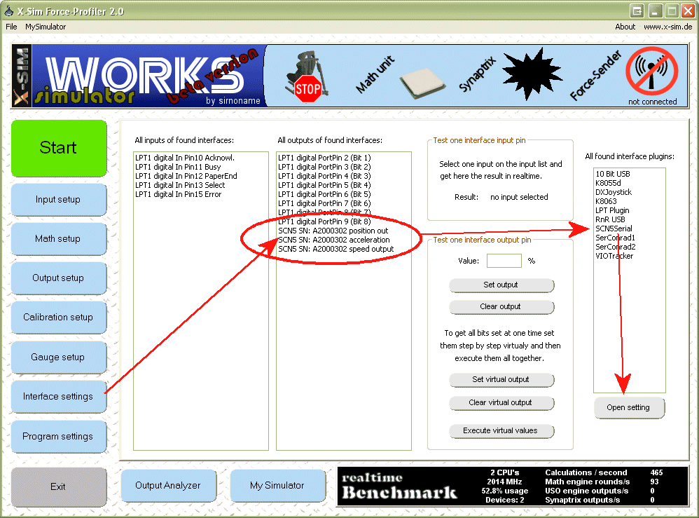
But normally you should use one comport for one SCN5.
After you have started the profiler2 application there should be a SCN5 listed in the interface setup -> output table.
If not: check your hardware, visit the hardware thread, ask there your questions!
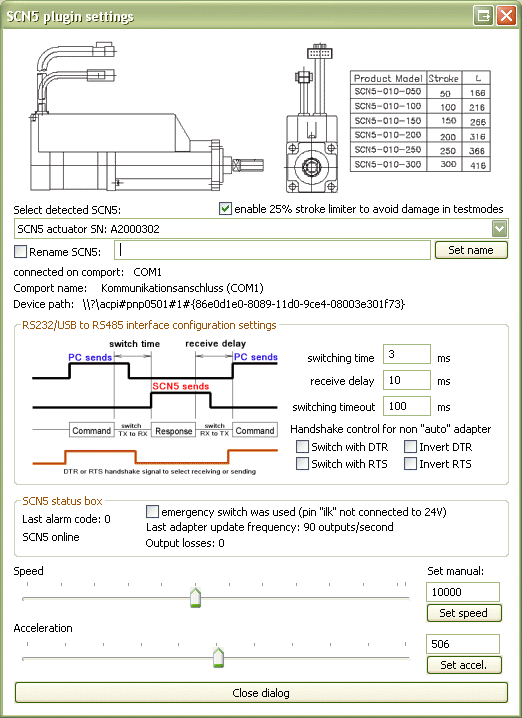
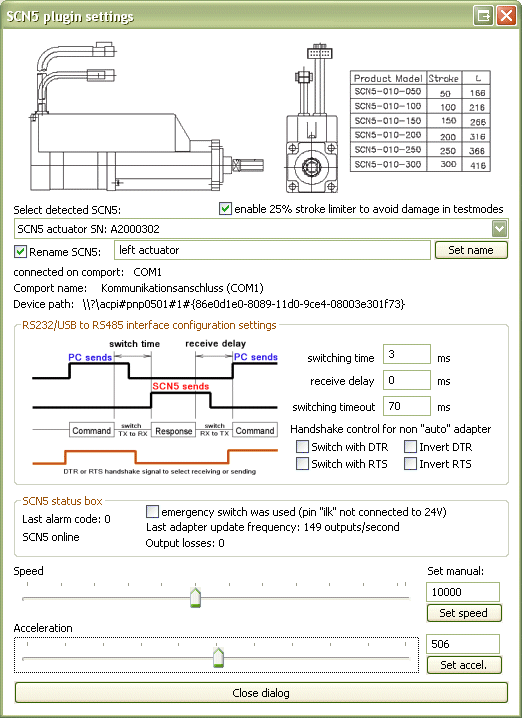
Now select in the plugin table the SCN5Serial entry and press the "Open setting" button.
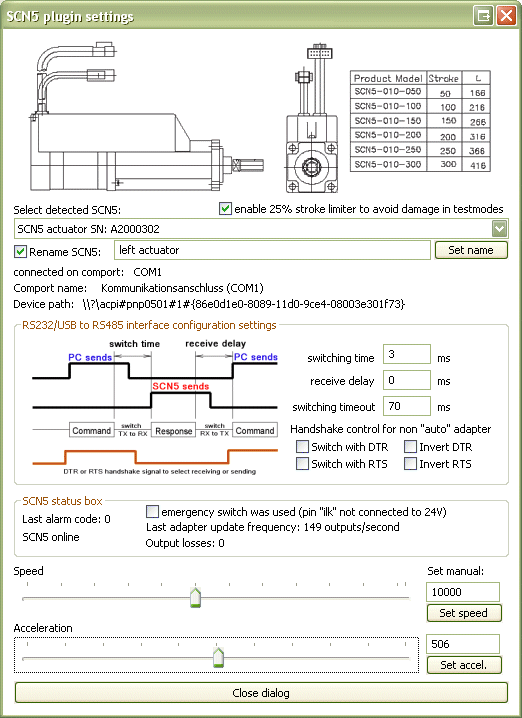
You can change the hardware controls DTR and RTS and the delay time for "auto" mode interfaces.
Automode interfaces do not need DTR and RTS and the do not care the settings made.
Manual interfaces do not need the delay time.
This three option are global for all comports and SCN5. You can not mix different automode and manual mode interfaces!
This setting window could be placed beside for later use, you should see all SCN5 modules in the combobox.
Change the SCN5 device ID if using only one RS485 converter
If you only own a single RS485 converter or USB device and like to try more than one SCN5, you are able to connect all SCN5 to the same bus system parallel. Before you do so, you have to change the device ID for each SCN5, so it will not response on a command of another SCN5. There are 16 device ID's possible to connect to one RS485 bus system. The SCN5 are delivered all with factory default values and device ID 0. This means you have to change a second SCN5 to a higher device ID number.
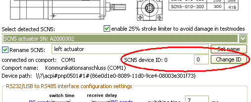
The x-sim SCN5 plugin dialog shows you the current device id and right you will find a box where you can insert the new ID. You are only able to change the ID, if this is the only SCN5 on the bus. Simple unplug the other ones at this comport and start x-sim again. Now you should only see one SCN5 available on this comport. After you have changed the device ID restart the application and insure the result is correct.
Please note: If you use more than one SCN5 on one comport the update rate will be divided by the number of scn5 connected. So if you have one SCN5 connected and reach 150 outputs/second (normal) and you attach a second one, you only have 75 output/second left. If you reduce this output/seconds you will notice this in the smoothness. (not in lag)
Step by step profiler configuration:
1. Insure SCN5 is detected and displayed
2. Start the sender application and select the test plugin.
3. let move the test slider 21 in auto mode
4. press "try connect" button
5. go to the math setup and insert a axis
6. insert a g-force with effect 21 and automode
7. now there must be drawn a sawtooth line
8. go to ouput setup and to Synaptrix IO
7. choose axis and a SCN5 as direct output
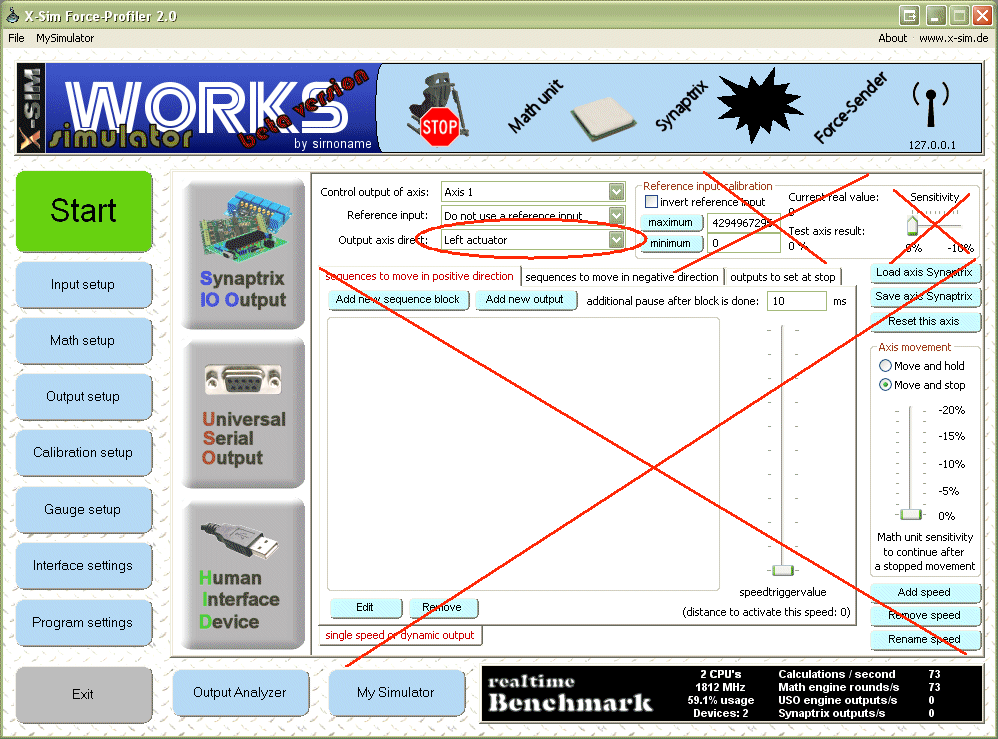
9. press the start button
Renaming SCN5:
The SCN5 comes with serial number as name, but you can give them better names. This is helfully, if you share your profile, so other know what they should exchange with this axis.
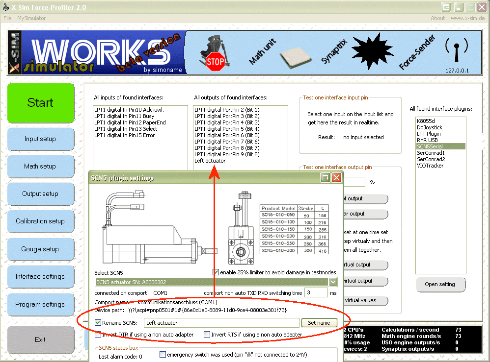
Enable the rename check box and enter a valid non doubled name in the edit box, else the serial number will displayed again.
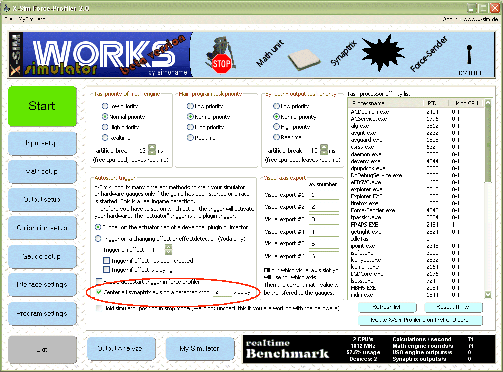
Center SCN5 after game has stopped:
Go to the program setup and enable the center option. Choose 2 seconds is enough.
Changing speed:
The sliders will tell you the current settings, you can change in realtime while moving.
Use also the smoothness add-on of the g-force math plugin to reduce bad hard movements.
Tips if the SCN5 is not detected
If you are using USB devices such as USB<->RS232 or USB<->RS485 adapters:
Download the latest drivers for that chip from the internet that is used in your adapter. This might be a FTDI chip or a profilic chip. Both need the latest drivers, FTDI have to change the standard response speed to "1" in the advanced driver setup (device manager).
Go to the hardware thread and compare the five point compare list, if your adapter fulfill the needs and the setup would be correct to reduce the possible combinations of errors you could have with the plugin.
If your adapter seems not to work, you can change into a step by step debug mode, which will tell you what happens on the profiler startup. If there would be a response but some other error occurs, you are able to see here any success.
Open registry editor and go to
HotkeyLocalMachine/Software/X-Sim/Force-Profiler2/Interface-Plugins/SCN5Serial
and make a Reg_SZ value with value 1. (0 to disable it again)
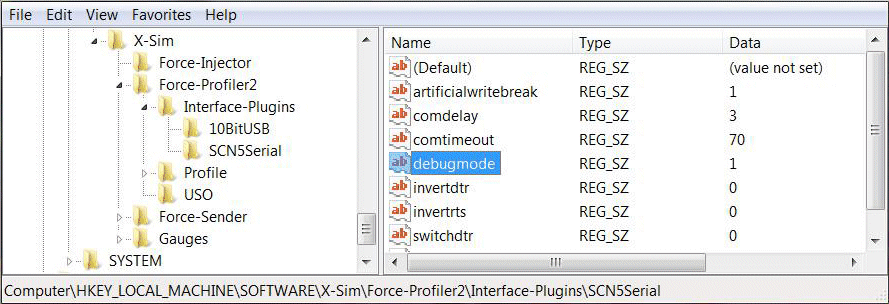
After this you will be noticed step by step about every comport detection with a message box.
If there is no response after a "SCN5 detection try", you don't get any response.
You can also compare the serial connection with the "free serial monitor".
http://www.serial-port-monitor.com/
If here comes no response you have to got to the hardware thread!
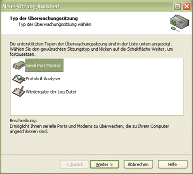
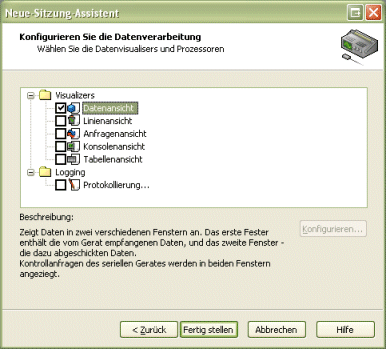
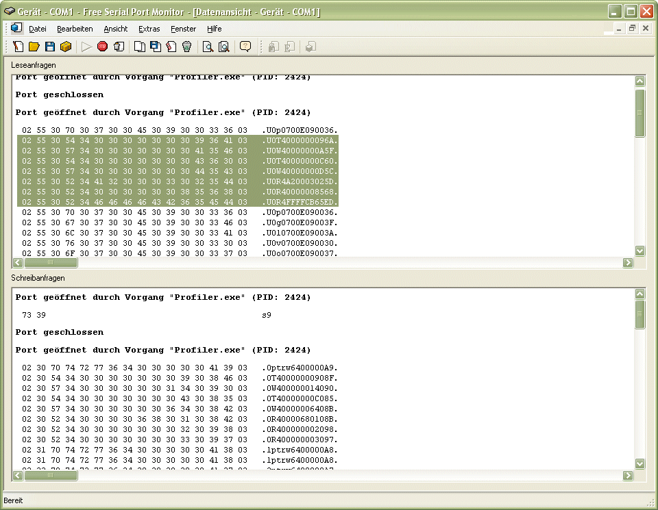
You can see highlighted the response of a SCN5 actuator. If the receiving area is blank, you do not get any response. If there are the same lines as in the sending box, your RS485 converter produce echos which are not acceptable for this plugin (timing). A echo you can see if there are some lines equal to the sended lines, this is not possible. (compare full line)
|