|
Using a electric drive is one of the greatest goals in the simulator building community. They are silent, are good to provide and small in their size.
The biggest questions and the answers (based on the current payable market):
Q: Which speed the actuator will need?
A: The goal is to reach a simulator movement in 1 up to 3 seconds from left to right, so a longer actuator needs more speed to reach that goal.
Q: Which acceleration/motor power do I need?
A: The acceleration depends on the motor type. A stepper motor will always provide a good acceleration while a gear drive needs more power to hold and start the gear movement. For simple balanced chair (like SimforceGT racing seat) movement it is normally about 50-100 watts (watt = ampere x voltage). If you go less than this values you are not able to drive vibrations.
Q: Which type of motor I should use?
A: Stepper motor will offer a big resolution and is more accurate than DC drives of same size. There are mechanical solutions to reduce that problem of DC motors which are cost intensive. A DC drive is more powerful than a stepper in fast movement. So the best solution for short movements up to 200 mm are stepper drives and the best solution for far movements are DC drives.
1. simplest DC electric motor relay solution
This type of motor use a positive voltage and a negative voltage. If they are inverted at the motor input terminals the drive will reverse its direction.
This is a relay standard solution which will simple switch with the maximum power of the motor. There is no speed or acceleration control.
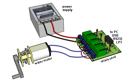
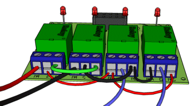
Red and black cables shows you the minus voltage or ground voltage (GND). The green cable is a optional brake cable which shorten the motor pins and produce a reverse magnetically field inside the motor which will work against the drill movement. The blue cables shows the outgoing motor cables which must can be loaded with the different polarization. The following closer sight will show you the correct wiring solution.
|
|
|
|
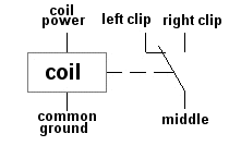
The left two relays will connect and disconnect the incoming power to the right two polarization relays. If you enable both right relays the two right relays should be placed correct else the power will be shorten. One of the right relays has to be enabled. The middle clip is the middle relay clip as shown right.
2. The PWM analogue DC motor control
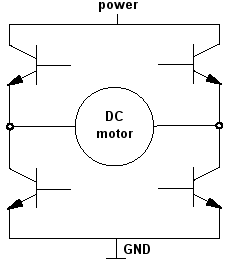
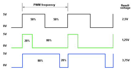
A advanced version of the simple relay solution is the usage of a H-Bridge which will not use relays but MOSFET transistors. The switching speed of these transistors is very high, so you can pulse the outputs very often. So you are able to integrate a analogue PWM signal to your motors. A PWM signal is a ON/OFF sequence with about 10kHz or higher. It depends on the used interface output frequency. More than 20kHz is not usual because the transistors are getting hot because they are hitting the level of power loss very often and loose some energy there. The outgoing voltage of a PWM output depends not on a frequency change but depends on the ON/OFF duty cycle in the frequency like shown below.
|
|
|
|
schematic of a H-Bridge
|
PWM pulse function that generates different voltages with a percent duty cycle
|
You will find the word “H-Bridge” very often in online shops or DIY (do it yourself) forums. At x-simulator.de/forum there are some DIY solutions of course. A H-Bridge is a separated part that must be controlled by a simple I/O interface with PWM output. Sometimes you will find a complete solution which is only suitable for one power output, so if you need more current you cannot exchange the H-Bridge in that interface board. Because the current (Ampere) is needed for the construction and decision for a PWM output, you have to know more about your DC motor. The simplest way is to measure the current with a multi meter in simulator movements worst case. This value you double to insure voltage spike injuries.
|
|
|
|
|
|
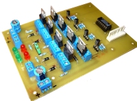
Thanos DIY H-Bridge
|
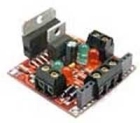
comercial H-Bridge with L298
|
|
|
As input all H-Bridges offers two pins for the direction and one as a global enable signal. If you bring the directions pins to the same level you have a brake or a no operation mode. If the direction pins are different the motor will drill in one of the two possible directions. You can use two solutions to bring in your PWM. One is to fix the enable signal to enabled and pulse the direction signal lines, the other is to fix the direction lines and pulse only the enable signal. The last solution is normally used.
As output they are connected direct to the motor. Also they own a power input with one ground pin. A H-Bridge which drives big current will not have a ground connection to the PC electronic to avoid conflicts with interference’s.
3. Stepper motor with linear actuator
The combination of a stepper motor with a linear mechanic is the accurate solution you can find. However stepper engines are not fast and the mechanic behind that stepper need to balance that limitation. Stepper actuators do not use a pot to get the current position. They use digital encoder which will count each step and therefore can exact get the current position. Because the encoder input is switching very fast, you cannot count this with windows operating system. The stepper actuators are always external intelligent actuators with their own encoder and amplifier electronic. The motor itself must be good balanced with the spindle. The fastest speed you can reach with a stepper which has only 100 steps per round and a spindle with a high gradient. Most actuator on the market do not offer this combination and therefore do not reach speeds above 70mm/s. You can only use them with mechanical lever shifter or other rod rope/cord solutions.
The best solution you can reach as buyable component
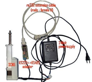
SCN5 actuator
 |