|
Using a pneumatic system is very easy, because there are many components out there from the industrial use or airbrush painting use. Also you can use pressure save tubes out of the market-garden. Additionally most pneumatic systems are driven by the X-Sim Synaptrix, so no expensive interfaces are needed here. Is I began to make my motion simulator my goal was to buy the legendary Rock’n’Ride pneumatic chair which was sold in budget shops in Germany. This is a simple pneumatic chair with two pneumatic cylinders and eight valves. All of these components are special produced for that chair and therefore not the best quality like from Festo, the biggest pneumatic parts company. However the general idea with eight valves and 2DOF are one of the most DIY projects we have solved in the X-Sim history. Because air is good to compress, the pneumatic system with low pressure is not able to hold a position really good. The precision will be reduced.
The Rock’n’Ride comes without a pressure tank included, but this will additionally increase powerfully movement all the time.
There are now many different solutions to build a pneumatic system. The samples below are only the basic ideas which are often used.
1. The 4 valve per cylinder solution
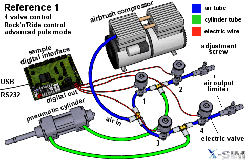
This solution is build in the Rock’n’Ride chair and offers some special features. The general assembly is shown in reference picture 1. There is a compressor which produce about 2-3bar of pressure. This is cylinder dependent. A small cylinder with low pressure usage will give you the change to use a small airbrush compressor, which is very silent. Big compressors out of the building and construction industry are very loud and not suited for home room usage. The pressure will be splitted into two separated valve input ports. Every valve is a “unpowered closed” valve which will not throughput any air if there is no power on the valve coil. If you will give valve 1 and 4 power, the compressor air will flow in the right cylinder chamber and the left chamber is opened. This will produce a movement of the cylinder piston to the left. If you are closing valve 1 and 4 again and open valve 2 and 3 the movement will be reversed. The airflow limiter on the outputs will control the movement speed for left or right. Use two limiter of you use a asymmetric simulator axis to synchronize left and right movement or up and down movement (i.e. for a heavy monitor mounted on the forward/backward movement)

Normal sequence of a pneumatic movement
|

|

|
|
all valves are closed
|
valve right opened and valve left connected to compressor will produce a movement right
|
The softmotion/pulsemode idea with 4 valves per cylinder (realized for Rock’n’Ride)
|

|

|

|
|
all valves are closed
|
only right valve connected to compressor, air left will be compressed and a slow movement to left is generated
|
valve right closed, valve left opened, the air will move out very slow, because the new pressure is missing from the right side.
|
2. Usage of a 5/3 valve systems
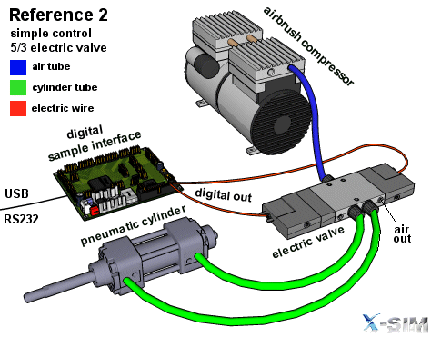
The 5/3 valve is a combination of valve 1 and 4 out of reference picture 1. These two valves are a single valve also valve 3 and 4 builds one valve. Therefore this valve block needs only two digital output port of any interface to make a cylinder movement. One coil will do two actions in this case. Because you cannot control all air inputs and outputs itself, the soft motion like described in 1.) cannot work here. But you are able to open and close/close the valves very often in a second. This will produce a impulse movement which is balanced by the inertly air compression. A pulse mode is not the best solution in this case.

3. Usage of a analogue airflow valve with a 5/3 valve as direction switch
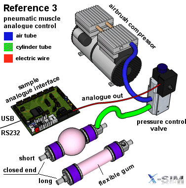
A combination of a analogue valve with a direction valve will solve the pulse mode problem out of 2.) above. You will control the airflow and therefore the movement speed with a analogue valve which is able to half open its switcher. You have to generate a PID synaptrix or you can make your own speeds without the need of PID control. You will need a supported analogue output interface like the vellemen K8055d. Also most of the analogue valves does not support 0 to 5 volts at their inputs, so you might use a analogue amplifier circuit.

4. The pneumatic muscle
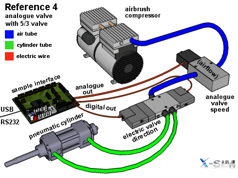
The pneumatic muscle is a piece of gum tube which is able to be inflated with high pressure. If the tube is like a balloon filled, the actuator is shorter than without the pressured air in it. The control is a voltage following electronic that will measure the output pressure and release some air if it is too much pressure or open the valve to the compressor if there is less pressure behind the valve. It is not a throughput valve, which only half open the valve way. This is a very instable actuator which must be mechanically stabilized by the constructor. Some only hang the simulator chair in a wide metal frame like a hammock.

|