|
The standard serial RS232/RS485 interface of X-Sim
USO is a smart interface to make a good start for interface developer and interface user. USO is the short synonym for Universal Serial Output. With this dialog it is possible to tell a serial interface a axis output or tell it a gauge dashboard value out of the gauge setup or math setup. Most interfaces use a simple way to receive values. Most they have a “STX” called beginning byte. This will tell the interface that there is coming something. Here we choose the letter “S” for start. Also most interfaces use a end byte, here we call it “E” for end byte, the “ETX”. Between these two notations there will be the real information. If there is no STX and ETX the interfaces will not hear the real information’s. Additionally there is often a checksum used, which will give back a smart overview if the real data’s are transferred correct. If the checksum does not fit, the interface will not accept the data’s. The data itself carries also some short commands and the values out of the X-Sim software. For example if you will send the value “3” to the output zero of an interface there might be following combination used:
“S03E”
S stands for the STX start command, 0 is the output zero and 3 is the value for this output, finished with the E for the ETX end byte.
This letter by letter command line will be read by a “parser” function, which calculates the resulting USO output to the interface.
How you find out what you have to send:
This is your most important research part if you are using the USO interface. First you have to read the manual of the used interface and look in the developer internet forums for samples of source code or discussion groups about this.
After you found some notice how it could work you can continue with the X-Sim2 USO dialog.

You have to fill out many different settings here, so let us begin with the main settings.
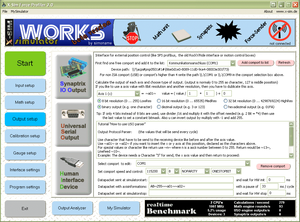
Step 1: Add the used comport
Select a found comport out of the top combo box. If your comport is not listed there insure the correct wiring of your adapter. Perhaps the USB adapter is not connected. If you have selected your comport you can add this by pressing “Add comport to list”. Now the comport will be listed in the lower comport combo box and will be used every time you start the profiler again.
Step 2: Set your comport settings
Read the manual of your interface what are the comport parameters for this module. You have to insert a comport speed in baud, a bit depth, parity and the stopbits. Hardware handshaking is not supported. This because there are too many possible methods on the market. Also windows is not really able to control DTR and RTS lines with the precision that would be needed. A RS485 converter with that handshakes are not usable, use auto adapter instead. (SCN5 interface)
Step 3: Data packet sent at simulator start
This line is not often used. I can handle some commands to the interface to startup the engines or to wake up.
Step 4: Data packet with axis information’s
This is the most important packet you have to create. Here the axis result values are transferred to the interface. As described above you have to read your manual what the interface want as input packet. Bytes who cannot be displayed as ASCII letter have to be written in “~”, so a STX with value 2 is ~2~. At the place where a axis data has to be transferred you have to write this axis also in ~a01~ style. The axis value can be in ASCII letters or in byte values used. Also it is possible to send the value in one single byte (0 up to 255), in 16 Bit format (0 up to 65535) or with extremely high resolution of 32 Bit (0 up to 4294967296). Please note that the middle position will always be the half, so if using 8 Bit the middle output is 127. In the math section the value 0 is at the bottom of the math diagram. The values are automatically scalled for what you are using. The above entry shows a STX of “AB”, a command byte for output “~255~” and the output of axis 1 and 2.
Step 5: Set update times
After a command is written, the interface normally will work for some time. Also it will send back some information’s. The USO interface will not receive this information’s but has to wait until they are sure transferred and the interface would be ready again. Choose a wide enough wait delay for this actions where X-Sim has to wait. After this time period the next packet will be sent to the interface. Windows is not able to drive exact time intervals. The time is always a double of two. So if you insert time values in ms steps it might not take effect and only increasing it to the next double of two will increase the executed time period.
Insert the values for all three parser lines.
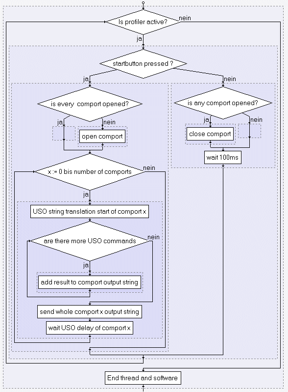
If using two or more comports: please do not insert a delay on the second comport, use zero instead. This because of the loop that structogram (1) shows you below. It shows you that the USO function will work step by step. The synaptrix will produce one asynchronous thread for one axis. The USO will only use one thread and works its parser step by step, comport by comport until it reaches the end. So one delay in that loop is enough, else you loose your output rate.
Step 6: Datapacket sent at a simulator stop
Before the comport is closed this packet could be used to disable the engines or to send the interface in a sleep mode.
Structogram (1) of the USO function

|