|
The fast and simple direct output of the synaptrix dialog
The direct output is a separated feature which will send one single analogue or digital export out of the math section to one single output which is assessable by the interface setup section. It is like the universal serial output, but uses complex interface plugins. You can output a analogue voltage level to a interface like the velleman K8055d and use that analogue voltage for a industry actuator that is using a voltage following control with its own electronic. This is also used for the SCN5 actuators. This output section is a addon which will not use the rest of the synaptrix dialog.
If you will control a complex sequence for a output this section will be left unused.

The Synaptrix dialog
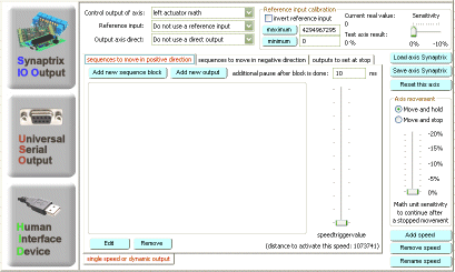
The synaptrix is a teachable motion control system. It is a advanced setup for users who know the sequence setup for their motion controler or linear actuator. It is a list of action to do. This action will be executed step by step. So you are able to tell the input dialog a detailed relay or valve sequence to move your actuator in one direction. Also the matrix for the reverse direction must be filled. And as last action you have to insert your actions for a stop condition.
1. Find out the connected ports
As first step you have to got to the interface setup and check out your hardware connections. You must write down your used output and input ports. Therefore you are able to read and write to all the listed ports in the interface setup. You need a pot or encoder feedback which tells you the current actuator position. This position feedback of the pot must be direct measured on the actuator. Also you need the port names to control the actuator vales, relays or H-Bridges.
2. Choose your axis
The actuator position will be compared to a result value out of the math setup section. There a ingame value will be generated which will be unified to a value from -2147483648 to 2147483647. For a actuator there is no negative value, so you can only use 0 to 4294967295. This is the same value, but free from the negative sign. All hardware ports use only 0 to 4294967295. Choose now a resized ingame value by create one axis in the math section and select this axis name in the synaptrix dialog. This will be the game compare value.

3. Set the reference input port
The position feedback need to be calibrated. You must know, that all inputs are scaled to a 32 bit value as a unified compare value. All input plugins have to resize a simple value like 8 bit = 0 to 255 to a unified 32 bit value of a range of 0 to 4294967296. You have to insure a complete usage of the maximum input value you are using. This can only be done mechanically. You pot should for example use all the 256 positions of a 8 bit analogue input. If you reduce the pot range you reduce the precision of your actuator system. If you select no input value a middle value will be set. This could be used for analogue output without the need of a position feedback (very rare used). With X-Sim 2 you are able to use simple joysticks as a input or a interface input as you like. Also you are able to mix them as you like. A joystick might use a better pot and analogue to digital converter electronic than a normal interface will ever reach. You are also able to use endpoint switches instead of analogue control.

4. Calibrate your reference input port
You have now to tell your setup which pot value is the maximum value to reach and which the lowest value could be. There is a calibration routine in the calibration setup dialog where this calibration can be simplified for later use. But for the calibration setup you have to fill out the steps behind 5 and up to get a motion.

After you have selected a input value this value is displayed for you in realtime in the calibration box. Now move your simulator without the actuators to the mechanical endpoints. This endpoints must be absolute mechanically secured. You are not able to connect a pot to a actuator and use only half of the way for a pot whole way. This would break your pot mechanically. The mechanical end positions are the important construction you will need. On each maximum position (positive and negative motion direction) you have to set maximum or minimum value (Maximum is the higher one). If your pot seems to be fidgety you have to reduce the sensitivity in a later step.
5. Setup the positive and negative direction actions
Now we will start to set up one of the two possible directions of a actuator. The positive direction is the direction where the pot will increase its value. You have to tell the dialog what the control thread has to do to get the actuator moving in the positive direction. This must be verified with the interface setup section before. At this point you must have advanced knowledge about what you do. For this tutorial we use a very simple example with a pneumatic actuator and a 5/3 valve. Now look at the picture and understand what we have to move in this tutorial.
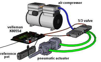
For more actuator descriptions you can look at the pneumatic, hydraulic or electric setup solutions in a short overview in the menu left.
This is a simple pneumatic setup that will move the actuator to a position that will be compared by a reference pot which is connected with a small rod to the actuator moving part. The 5/3 valve can do two actions. If the left side is activated, what means the valve coil is powered, the air flows in the actuator and the piston will move the stick. If the right valve is activated it will cause a reverse direction to the stick. Both activated are a senseless mode. This sample will only move with one speed which is generated by the air pressure of the compressor.
Now we look closer to the valve which causes a outgoing stick movement. As told before, you have to find out which port will activate this valve in the interface setup section.
Now we choose the positive direction tab and press the “add new sequence block” button which will cause a new entry with a sequence block 1. The delay after this block is how often you will do that in a second what means the whole compare circle. A whole compare and control circle includes pot measurement, compare to ingame value and execute a fitting valve control for a movement to reach the ingame value.
We now add this valve setup to move the pneumatic cylinder out by pressing “add new output” button. In our case we have the valve connected to a LPT digital output pin which we will now enable to enable the valve.
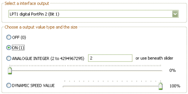
Now the valve will be activated every time we need a movement in the positive direction.
But wait:
It is always necessary to insure the other valve is not activated, so we have to add another output which will close the other valve!
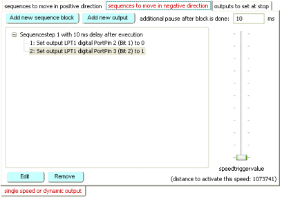
Do the same in the reverse direction, but set your ports here inverted.
The following result should do the correct movement in the positive and negative direction in our sample.
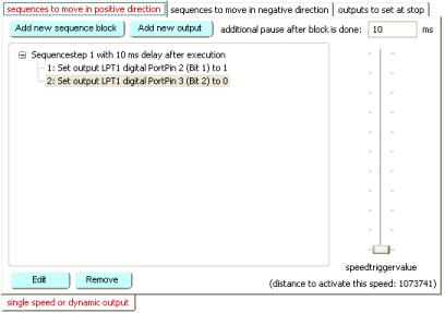 
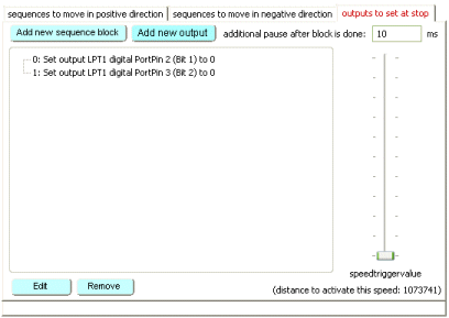
Last but not least the setting for a stopped movement is missing. In this dialog you can only set outputs to high or low but not a sequence of more outputs which are changing in a specified interval. So you can not add a sequence like in the other direction dialogs..
Now you are finished with the matrix setup for this axis and you can continue with the next axis.
5 a.) Use two speeds
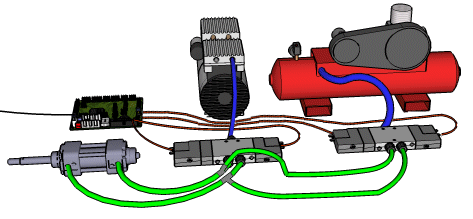
If you are not able to get a dynamic valve, you can use two different pressures in pneumatic or voltages in electric actuator systems to get a slower motion. This is needed to avoid the acceleration forces from your simulator. The picture above shows you a second pneumatic compressor (red) which will generate a higher pressure and therefore moves faster the actuator if the valve system of this compressor is used. You have to add a new speed tab in your profiler to tell the software when it should use the red compressor and when the smarter compressor. Notice that you have now to close the valves of the slower speed valves in the faster speed and contra wise.
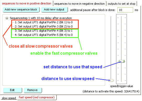
The speed trigger value is a symbol of the distance that the new ingame value is away from the current actuator position. If the distance is reached, this speed tab is used. It is a range from the last speed (left slider) to the current speed. The following speed range is displayed with a slider right. In our case the slow speed will be used until the distance to the target value is higher than 326417514. You have to setup this as the above description told you for every actuator movement direction and stop mode. Always remember to close all valves.
5 b.) Pulse mode setup
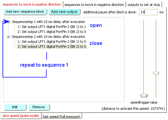
With the pulse mode function in the synaptrix you are able to drive sequences of enabled valves. A simple explanation is if you like to add a second speed without a second pressure in the above sample. You can simple switch the valve 10 ms on and 10 ms off which results in a slower motion. With this trick you are able to simulate a slower speed and add this speed for accurate movements that are not far away from the current actuator position. The advanced solution you will find in the pneumatic section, where the soft motion solution is declared. This solution only works with the 4 valve/actuator solution. The 5/3 valve is not able to switch air out and air in separately. A sample of the soft motion idea is located in the “my profile” directory of X-Sim2. This sequence is used with the RnR 1.3 interface and 8 valves to control two actuators with soft motion pulses.
To add such sequences you simple have to add a new sequence and over give the wished sequence speed with the additionally pause.
6. Special functions
As a final step you are able to setup some special functions. The move and hold function will not always poll your simulator and waits for new ingame values. This is good for pneumatic systems. If the driver moves left or right the simulator will also move because air cylinder are very easy compress able. If the simulator moves, the software will normally move against this. This would be a endless moving. If the “move and hold” function is activated it will move the actuator to its end position and waits not for a new simulator feedback but for a new ingame value. The sensitivity of the ingame detection is the slider below that option.
|